Fixed Center Drives – Series 45
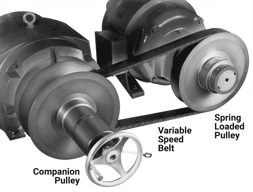
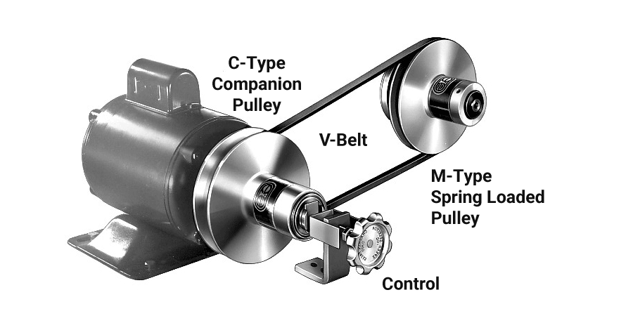
The Series 45 consists of three drive system components: a mechanically operated driver pulley mounted on the motor shaft, a spring-loaded pulley mounted on the driven shaft, and a variable speed belt running between the two pulleys.
Output speed is reduced by turning the handwheel on the motor pulley, while the drive is running, to mechanically open the pulley face. This allows the belt to drop down to a lower pitch diameter on the driver pulley, while spring pressure in the driven pulley forces the belt to a higher pitch diameter. Speed increase is accomplished in exactly the opposite manner.

Series 45 Pairs
The following list pairs a spring loaded pulley with a controlled pulley to meet a wide range of operational needs.
Model 406 – Model 5116
Model 407 – Model 5128
Model 409 – Model 5151
Model 411 – Model 5112
Model 414 – Model 5122
Model 414 – Model 5133
Model 417 – Model 518
Model 419 – Model 520
Series 45 Installation Alternatives
Series 45 Pulley Mounting Details
Fixed Center Drives – Series 21
- Standard V-Belt Drives
- Permanent Lubrication
- High Ratio
- 1/4 to 5 H.P.

Series 21 Drives
1/4 thru 1 H.P.
2, 3, 5 H.P.
Series 21 Drive Selection Table
Series 21 Belt Selection Chart
Checklist for Drive Selection
Determine Motor Speed and Horsepower
- Series 45 – select the drive that satisfies these conditions. Choose from the Fixed Center Pairs list above.
- Series 21 – Select the range of drive combinations which fall into your requirements.
Determine Driven Shaft Speeds Required
- Check the driven speed range or your selection and compare it with your requirements
- Note alternative speed ranges available with 1200 and 3600 RPM motors
Determine Center Distance Between Motor and Driven Shaft
- Series 45 – Select the proper belt by refering to the belt vs. center distance chart on the fixed center pair
- Series 21 – Select the proper belt by refering to the belt vs. center distance chart on your chosen combination
Determine Motor and Driven Shaft Diameters
- Series 45 – Specify the proper bore sizes on both motor and driven pulleys. Specify driven shaft configuration as either standard, through bore, or reverse bore. See Installation Alternatives.
- Series 21 – Refer to the dimensional data for your selected pulleys and confirm that the shaft diameters are within the pulley’s design limitations
Check Your Power Requirements at The High and Low Speeds
- Series 45 – Compare your requirements with the rated power curve on the fixed center pair