Drive System Dimensional Data
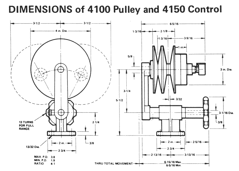

- Spring-loaded belt face to insure proper tension
- Unique control mechanism
- High-speed ration using standard A section belts
- Ratios up to 4:1 available
|
H.P.
|
Speed
|
Motor Pulley Diameter
|
Driven Shaft Diameter
|
|
1/4
|
437-1750
|
2.0
|
4.0
|
|
282-1130
|
6.2
|
||
|
218-910
|
7.7
|
||
|
180-712
|
9.7
|
||
|
1/2
|
656-2630
|
3.0
|
4.0
|
|
425-1700
|
6.2
|
||
|
340-1360
|
7.7
|
||
|
270-1080
|
9.7
|
||
|
3/4
|
875-3500
|
4.0
|
4.0
|
|
563-2260
|
6.2
|
||
|
455-1820
|
7.7
|
||
|
361-1145
|
9.7
|
||
|
Service Factor 1.2
|
|||
|
Note: H.P. capacity as shown is from Mid to Max speed.
Rating is 50% lower at low speed. |
|||
|
WARNING: All open belt drives must be adequately
guarded for personal safety during operation. |
|||
|
Belt No.
|
Motor Pulley Diameter
|
||
|
2.0
|
3.0
|
4.0
|
|
|
4L200
|
5.8
|
||
|
4L220
|
6.8
|
6.0
|
|
|
4L240
|
7.8
|
7.0
|
|
|
4L260
|
8.8
|
8.0
|
7.2
|
|
4L280
|
9.8
|
9.0
|
8.2
|
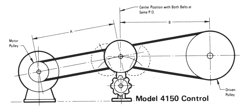
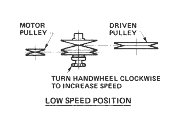
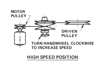
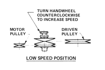
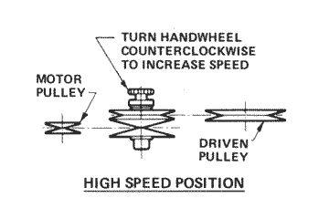
Compound Drive Installation Configurations
The diagrams below illustrate the proper methods of installing compound drives. Any other menthod of installation will result in severe belt damage. Choose the configuration which best suits your application.
